Shelter Frame Wind Load Analysis
A Shelter Frame Analysis begins with a shelter drawing from the client. The drawing is converted into a 3D SolidWorks model which is imported into SolidWorks Simulation Beam Analysis where the individual shelter frame members are converted into beams with the same material and geometric properties as the original shelter frame.
Wind load pressure is determined using methods outlined in AISC 7-05. These wind load pressures are converted to wind load forces by multiplying these pressures by shelter covering areas. A sample of these wind load pressure to wind load force calculations are shown on the bottom right of this page. The calculations were performed using MapleSoft Mathematics software.
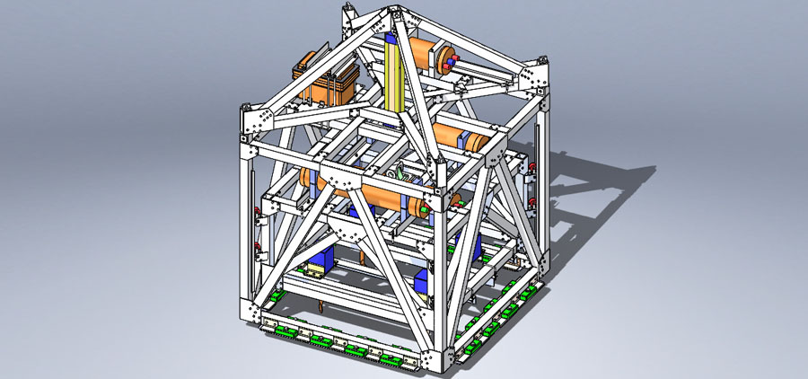
SHELTER FRAME SOLID MODEL AND STRESS PLOT

Shelter Frame Solid Model and Stress Plot Explanation
The image above shown a solid model and stress plot of a 52 ft x 40 ft shelter structure. The structure was modeled and analyzed with SolidWorks Simulation Beam Analysis software. A wind load of 120 mph at a direction 45 degrees relative to the structures roof ridge was used in the wind load analysis. The stress plot shown in the bottom image indicates that the maximum stress in the structure is about 32 ksi at the location indicated by the label on the stress plot.


Connect With Us